The Frame and The Drivetrain

The Frame
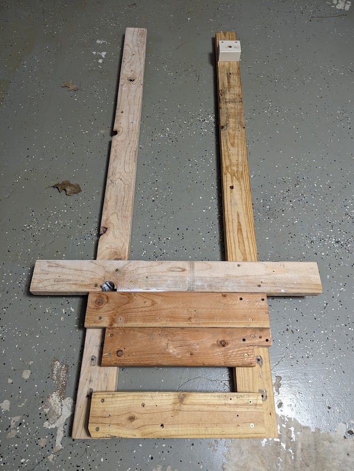
The whole frame is constructed from 2x4 Home Depot lumber studs. As a classic body-on-frame design, there are 2 long, horizontally assembled bearer studs with short cross members holding the whole construction. Initially I thought the result will be flimsy and multiple reinforcements will be required, but it appears to be a great design choice (I am 176 lbs was comfortably driving a big 250 lbs friend).

I built the frame twice "playing" with it's length and width. The distance between the main studs (11 3/4") is chosen after several attempts and is mostly dependent on Rear Live Axle size which is 740mm. It also accommodates the 2 seats - so the bearer studs are exactly between passenger legs.
The length of the bearer studs which is practically equivalent to the length of the vehicle is chosen to comfortably accommodate 2 adults (I am pretty tall - 6'2") without being wasteful in space.
Since our frame is built from wood, we can allow ourselves to make mistakes without compromising too much budget - if something is wrong we can quickly disassemble and rebuild from scratch.

Rear Axle and motor mount
The Rear Axle is mounted so the tires will end up slightly behind the bearer studs, this way it will later be possible to store the cart vertically.


Rear axle is mounted between 2 crossbars with the motor ahead of it.

The motor is mounted on top of 2 2x4 crossbars using 5/16 bolts.
Since we don't have any adjustment mechanism to adjust the position of the motor towards the position of the rear axle - it is extremely important to make sure the rear sprocket is fully aligned with the motor sprocket
Front Wheels Spindles
Front Wheels Spindles must be sturdy enough, therefore I used 48" steel "C-Channels" from Home Depot:


Steering Assembly

Our steering assembly is originated from a Chinese 110c Go Kart
Steering assembly consists of:
- The assembly itself
- Tie Rods
- Flexible steering wheel column
- The steering wheel
The steering assembly is mounted on 2x4 cross bar.

Since there are not any mounting points on the assembly, it took me awhile to figure out the best way to mount it. Eventually I used off-road bars brackets which are sturdy enough for this purpose:

Steering Wheel
I used 2 2x4 studs screwed together to build a steering wheel and dashboard vertical mount:

The exact positioning of the vertical mount on the frame stud depends on the position of the steering assembly, so I suggest mounting the steering assembly first, before positioning the steering wheel mount.
Hydraulic brakes
Seats
It took me awhile to find a not expensive seats of the right size with moving rails. Eventually I chose forklift seats which did the job well except being slightly on the heavy side. The seats have an adjustable backrest and it's distance from control pedals can be adjusted based on the height of the driver.
Electronics Enclosure
The electronic enclosure is built from plywood to have enough space for controllers, fuse board, and batteries. Jump to the electronics part to get the schematics.
